TYPICAL SYSTEM CONFIGURATION
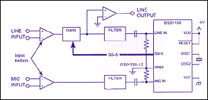
A typical system configuration is shown below. It consists of line and microphone input buffers, anti-aliasing and frequency weighting filters, a variable gain stage, and the
DSS 1100™.

Input buffers
These buffer stages serve to provide a high input impedance front end and the necessary amount of gain or attenuation. They can be either single-ended
(unbalanced) or differential (balanced), as the application requires.
Pre-filters
The analog-to-digital converters inside the DSS 1100 require the input signal to be band-limited to 5kHz. One function of the pre-filter is to attenuate signals above 5kHz. The signal above 5.5kHz must be at least 10dB below the passband. A more important role for the pre-filters is to frequency- weight the incoming signal to let the
DSS 1100 "work harder" to preserve the signal to noise ratio in some frequency bands over others. A , bandpass filter is suitable for speech and background music applications.
Gain block
This block provides a variable gain to the input signal as determined by the 6-bit gain bus from the
DSS 1100. The DSS 1100 is designed to work well with standard multiplying digital to analog converters (MDACs), such as the TLC7524. Tie the unused least significant bits of the MDAC high.
Output buffer stage
An output buffer stage may be required to optionally amplify and provide a low impedance drive.
The input dynamic range of the DSS 1100 is limited to the power supply. To accommodate this, the signals from the pre-filter stages may be AC coupled to the the
DSS 1100, with the DC level of each input pulled up to the midpoint of the power supply. This midpoint voltage is also fed to VREF for subtractive offset cancellation. The midpoint voltage does not have to be particularly precise or temperature stable, but must be decoupled sufficiently to attenuate power supply ripple to below 5mVpp.


